

Machine Movement Two Main Categories
The following points highlight the five chief types of charts used in move study. The types are: ane. Operation Process Chart ii. Flow Diagram 3. Man-Machine Nautical chart 4. Left-Right Hand Chart 5. Simo-Nautical chart.
Type # 1. Operation Process Chart:
This is a graphic representation of the sequence of all operations and inspections involved in the process. In this chart, all components or materials entry points are indicated past the horizontal lines and the processing of these materials are shown vertically. Operation process charts provide a compact overall view of the whole arrangement of operations involved in the manufacture of a production.
Process Nautical chart-Symbols:
In the process charts sequence of events are portrayed diagrammatically by means of a set of procedure chart symbols to help a person to visualise a process as a means of examining and improving it.
The basic symbols used in the procedure nautical chart to tape the diverse types of events are as follows:

The first five symbols are bones symbols and the terminal two combined symbols. The combined are used to represent the combined activities, the outer symbol represents major activity.
Types of Process Charts :
At that place are iii types of process charts and they are:
i) Outline process nautical chart.
2) Two handed process chart.
iii) Menstruation process chart.
i) Outline Process Chart:
An outline process nautical chart is the first footstep to a detailed assay of a procedure. It gives the overall view of the whole process past recording in sequence only the main operations and inspections. It uses but operations and inspection symbols.
ii) Two Handed Process Chart:
The two handed process nautical chart gives a synchronised and graphical representation of the sequence of manual activities of the worker. Information technology is chosen two handed process chart since information technology records the activities of the left hand and the right manus of the worker every bit related to each other. A time scale can as well be provided on the chart. This chart is used for repetitive works of curt elapsing.
iii) Flow Procedure Nautical chart:
A flow process nautical chart records all the events in sequence using process chart symbols and marks altitude and fourth dimension taken for completing an activity.
At that place are 3 types of catamenia process charts and they are:
i) Flow Process Chart (Men).
ii) Flow Procedure Chart (Material).
3) Menses Process Chart (Equipment).
The Flow Process Chart for Men records the activities of an operator.
The Flow Process Nautical chart for Materials records what happens to the material with respect to location and condition.
The Catamenia Process Charts for Equipment record the mode in which the equipment is used.
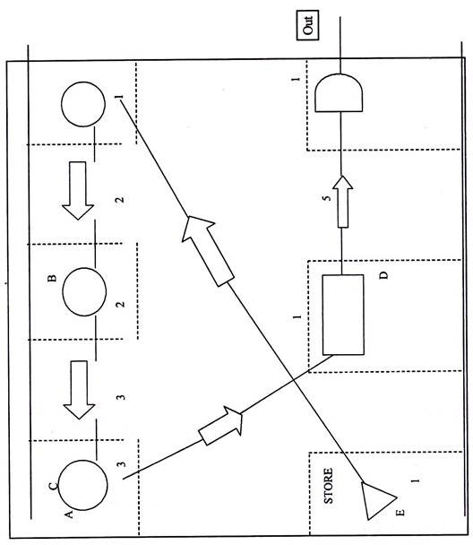
Type # 2. Flow Diagram :
A flow diagram is the simplest of all the devices in this form of technique. Information technology is the programme view of a work to a certain scale and link diagram indicating the path followed by the object under study. It gives an overall view of an existing or proposed procedure and is used for making improvements. It shows the path followed past the material, man and equipment.
The steps involved in cartoon a flow diagram:
i) The plan of the work area is drawn to scale.
ii) The relative positions of diverse facilities such as machines, stores, surface area of inspection and the like are marked.
iii) The actual path movements of a worker or material forth with the direction of motility is indicated. For improve agreement of different movements, different colours and process symbols may be used.
The above post-obit shows a flow diagram in that textile from stores move to place 'A' where one operation is performed. Thereafter the semi-finished production is sent to 'B' where another operation is conducted. Later on that it is moved to place 'C' wherein yet another operation is conducted. Then it is sent to identify 'D' for inspection. Thereafter it is sent to place 'Due east' where it halts for some-time and finally goes out of the factor.
String Diagram :
A string diagram is a special form of menses diagram in which a string is used in identify of lines to mensurate distance. This diagram is a layout drawing on which a length of string is used to record the extent equally well as the blueprint of motion of a worker or piece of equipment working within a express area during a certain period of fourth dimension. Information technology is used to report where the journeys are irregular in distance and frequency, otherwise information technology volition exist difficult to see exactly what is happening.
It is used to investigate movement in the following situations:
1. When a group of operators is working.
ii. When a unmarried operator is attending several machines.
3. In processes where several sub-assemblies have to be moved to other associates.
4. Where processes require the operator to be moved from one work identify to another.
five. For checking the relative values of layouts.
String Diagram Report Sail :
To draw a diagram first, study is made for the movements in the activity concerned. Every movement in the performance of the work is recorded on the report sheet.
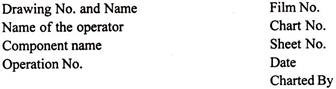
The string diagram study sheet contains the post-obit details:

Most of the cord diagrams consist of a calibration plan mounted on a soft board, with pins stuck in the relevant work stations. Additional pins to be driven in where the direction or moves between these points change. Thread of different colours tin can represent the various factors existence moved.
Type # three. Man-Motorcar Chart :
This chart explains graphically the activeness of a human being and auto he is attending with reference to a time scale. This report is undertaken to notice what number of machine each worker can operate or how many workers can piece of work on each machine.
This chart enables the direction to minimise the idle time of the worker and to employ the machines to their total chapters. For case, there are three workers and each worker is doing the same operations on automobile. In that the time to ready a motorcar cycle is 0.50 minutes and machining time taken 0.75 minutes.

From the figure it is clear that for each operation, the worker is idle for 0.75 minutes, when the machine is running. For this, the alternative can exist to put two machines and let let one worker to work both on them.

At present the worker still remains idle for 0.25 minutes in each operation. In gild to minimize this, i more worker is allowed to work on three machines.

Type # iv. Left-Correct Hand Chart :
This is also known as two handed process nautical chart. Information technology gives a synchronized and graphical representation of the sequence of transmission activities of the worker. This type of chart is used to improve the motion sequence of an operator.
It is called 2-handed process chart since it records the activities of the left mitt and the right hand of the worker as related to each other in a two column chart by ways of symbols aligned representing the simultaneous movements of both hands announced reverse to each other. The nautical chart is used to minimize the unnecessary motions and to arrange the remaining motions in an economic way.
The ii handed procedure chart is given below:


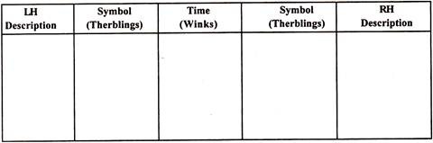
Type # 5. Simo-Chart (Simultaneous-Motion Nautical chart) :
Simo-Chart is an extremely detailed two hand chart. A Simo-Chart is often based on film analysis. It shows a mutual scale the Therbling or groups of Therblings performed past different parts of the trunk of 1 or more than workers. The time scale is represented in winks (ane/2000 of a minute).
Simo-Chart is used for micro motion analysis, for case short cycle repetitive jobs like inspection, packing etc., and loftier order skilled jobs like component associates. A Simo-Nautical chart shows the relationship between unlike limbs of a worker with records of duration of micro motions. For example, at an instant it can be constitute what one hand is doing with respect to another in terms of therblings.
Steps for Amalgam Simo-Chart :
1. Using a 16 mm moving picture camera micro motions are filmed as the worker performs the job. A wink counter i.east., a timing device is placed in the field of view.
2. The film thus obtained afterward a whole cycle, is viewed for assay.
3. The work study engineer analyses the moving-picture show, frame by frame concentrating beginning on the left manus and then on correct mitt movements.
4. The data noted in footstep-iii is recorded in the form of therbling chart. The elapsing of actual movements are as well read from the wink counter.
5. A Simo-Chart is prepared at this stage for farther written report and analysis.
6. This Simo-Chart of the existing method is subjected to a questioning procedure based on the principle of move economy. The purpose is to develop a meliorate and improved procedure.
7. A new Simo-Chart is now prepared for the new method.
8. The new method is now checked to claim its advantages over the sometime method.
Simo-Chart contains the following details:
A Simo-Nautical chart is advantageous because it permits very authentic and detailed analysis. The piece of work bike from the film can be studied at ease, peacefully and away from the disturbing surround of the piece of work place. However this technique is limited considering of high cost of filming and assay.

Machine Movement Two Main Categories,
Source: https://www.economicsdiscussion.net/engineering-economics/charts-used-in-motion-study-5-types/21703
Posted by: gonzalezabte1968.blogspot.com
0 Response to "Machine Movement Two Main Categories"
Post a Comment